|
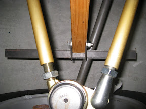
 The wooden jig was made from a piece of 2x2 pine with each end trimmed a little bit to simulate the 1 3/8" width of the bushing tubes. A through hole was drilled on each end at a distance of 12.5 inches from each other. This represents the midpoint of the coil-over shock's extension, allowing for 2.5" of compression and 2.5" of droop. This approach assumes that the effective spring rate and the weight of the vehicle will compress the spring exactly halfway when fully laden with passengers, fuel, etc. The wooden jig was made from a piece of 2x2 pine with each end trimmed a little bit to simulate the 1 3/8" width of the bushing tubes. A through hole was drilled on each end at a distance of 12.5 inches from each other. This represents the midpoint of the coil-over shock's extension, allowing for 2.5" of compression and 2.5" of droop. This approach assumes that the effective spring rate and the weight of the vehicle will compress the spring exactly halfway when fully laden with passengers, fuel, etc.
It is important to replace the wooden jig with the actual coil over spring assembly during this mock-up stage to be sure that the diameter of the spring does not interfer with the upper control arm cross member. This was a factor for my build, so I decided to run the coil-over shock upside down. This provides more clearance because the spring is held in place by the spring perch a good 4 inches away from what most people consider the "bottom" bushing. I can't think of any reason why "upside down" would be a problem since these are single-tube, pressurized dampers... but please let me know if you have specific knowledge to the contrary.
 Another factor to consider during trial fitting is the amount of clearance between the spring and the upper control arms. I decided to center the coil-over relative to the upper control arm for maximum clearance. This required placing the lower shock mount toward the rear of the control arm, as shown here sitting on top of a piece of flat 1" for mock-up purposes only. A proper piece of 1" square, heavy wall tubing will be notched and welded in place to complete the letter A shape of the lower "A-arm". Another factor to consider during trial fitting is the amount of clearance between the spring and the upper control arms. I decided to center the coil-over relative to the upper control arm for maximum clearance. This required placing the lower shock mount toward the rear of the control arm, as shown here sitting on top of a piece of flat 1" for mock-up purposes only. A proper piece of 1" square, heavy wall tubing will be notched and welded in place to complete the letter A shape of the lower "A-arm".
Two identically square-notched shock mount brackets were bolted to the bottom of the wooden jig, waiting to be welded to the A-arm portion of the lower control arm. With the chassis proped on wooden blocks to represent the static ride height, and while using the wooden jig to represent the length of the coil-overs at static ride height, the placement of the lower A-arm cross member (from a front view) is determined by the position of the lower shock brackets within the wooden jig. This approach should accomodate slightly longer or shorter coil-overs depending on your particular application. When selecting a coil-over length, it is generally best to place the lower shock mounting brackets as close to the lower ball joint sleeve as is reasonable, but slightly inboard is very common. As the lower shock mount moves away from the chassis, the front-view angle of the coil-over shock typically increases. This front-view angle really should not exceed about 40 degrees so as to avoid great stress in the suspension components. Exceeding 45 degrees at any point in the suspension's range could be detrimental to the entire assembly (tremendous stress on the parts).
|

